Reverse Engineering a Heat Exchanger Head in a Nuclear Facility
Location:
Maryland
Market:
Nuclear Power
Service:
Reverse Engineering & 3D Modeling
AT A GLANCE
Client: Nuclear Power Plant
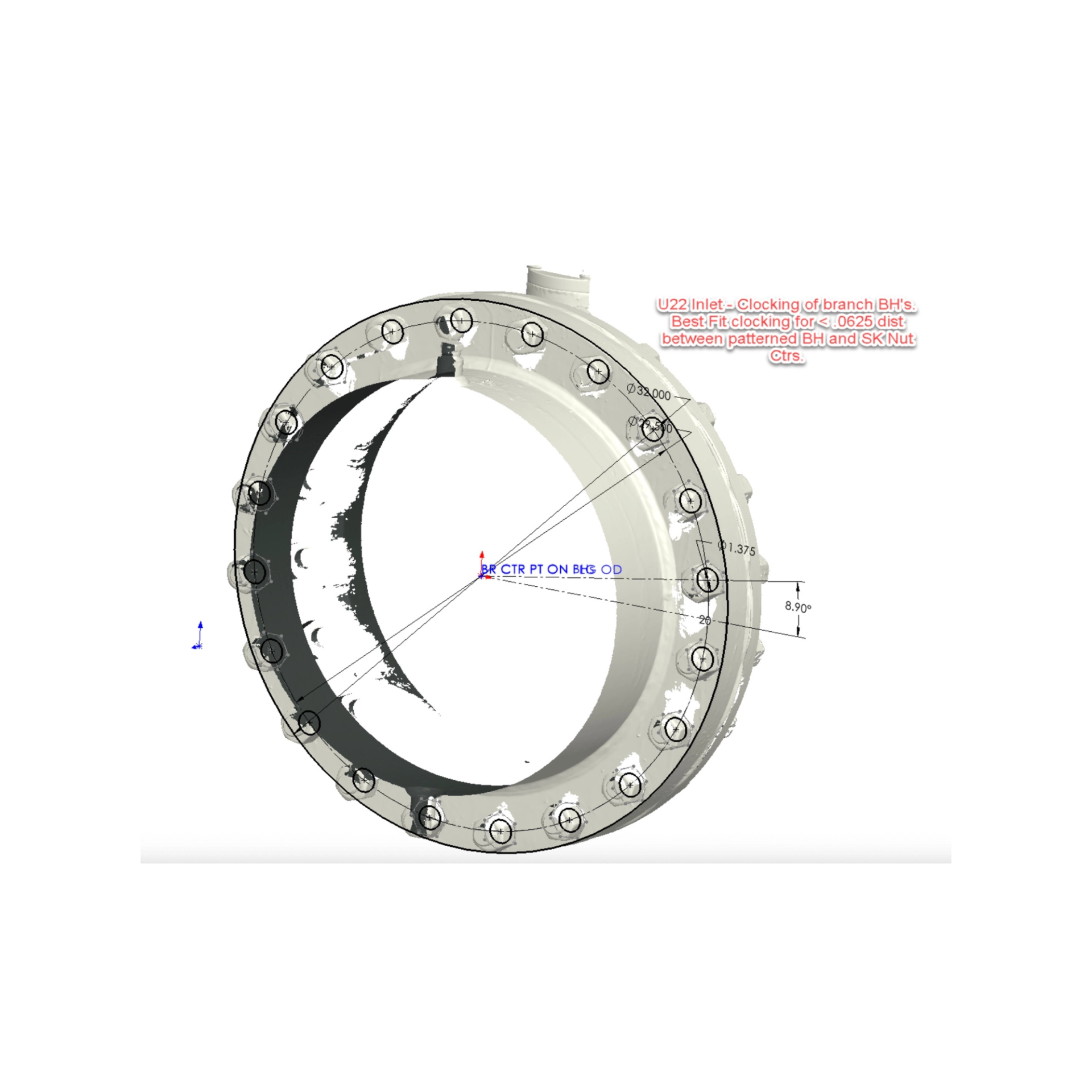
Need: Determine precise "clocking" of two welded slip-on flanges located on a heat head exchanger head
Target: Finding bolt-hole centerlines without direct access to the bolt holes due themselves
Constraints: Nuclear site restraints; no equipment can be removed
Partners: Master Machine (nuclear contractor)
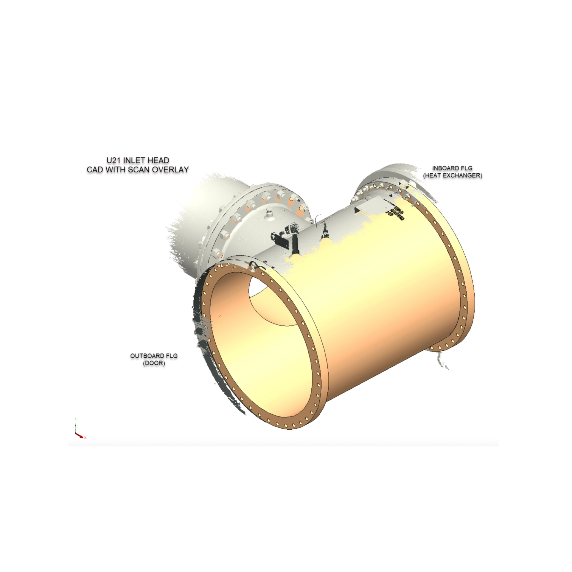
Result: High resolution field scan data of the exchanger head and flange assemblies, and reverse engineered 3D CAD models of the scan data
THE CHALLENGE
A nuclear facility in Maryland required the exact bolt-hole orientation ("clocking") of two field-fit welded slip-on flanges installed on a large TEE-shaped heat exchanger head. The information was needed for engineering and fabrication purposes, but the project came with a significant constraint:
- The heat exchanger heads could not be removed from service.
- The flanges had been field-fit and welded in place.
- All studs and nuts were required to remain installed throughout the project.
- Direct access to the bolt holes was impossible.
Because the equipment was safety-related and located within a nuclear facility, traditional measurement methods involving disassembly were not an option. The client needed highly accurate flange clocking data while maintaining equipment integrity and avoiding operational disruption.
OUR APPROACH
To overcome these restrictions, HAGLER deployed a metrology-grade field measurement team equipped with the ZEISS T-SCAN HAWK 2 portable laser scanner.
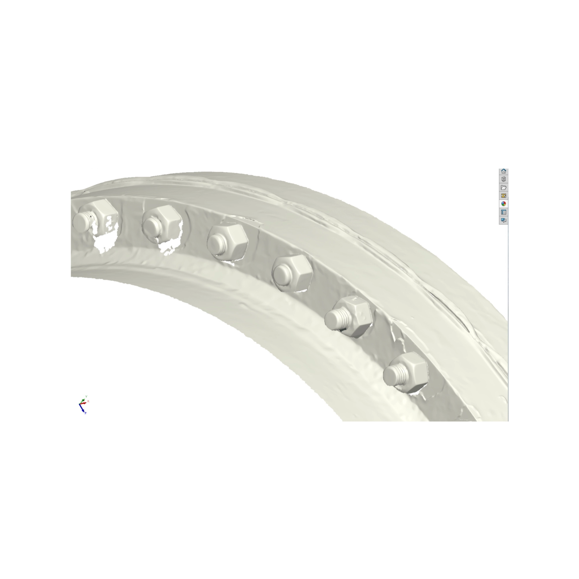
The team traveled on-site and performed high-resolution laser scanning of the heat exchanger heads and flange assemblies in their installed condition.
The workflow included:
- Capturing highly accurate scan data of the exchanger heads and flanges.
- Reverse engineering the scan data into detailed 3D CAD models.
- Analyzing the geometry of the installed studs and nuts to infer the hidden bolt-hole locations.
- Creating a best-fit bolt circle using calculated nut center points.
- Determining the exact bolt-hole centerlines and flange clocking orientation.
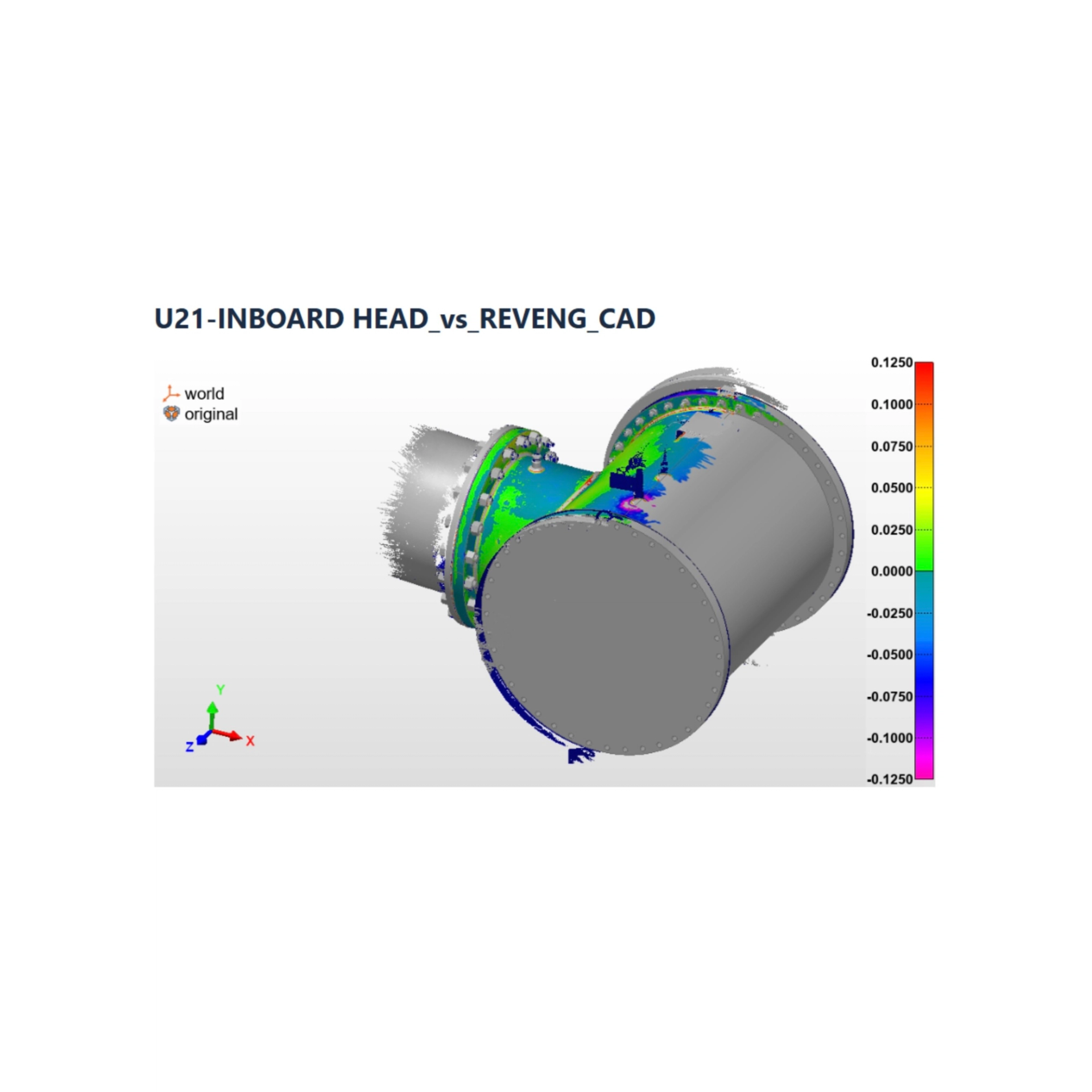
- Validating the final CAD models against the original scan data through deviation analysis.
The result was a complete digital representation of the installed equipment without removing a single critical component.
KEY HURDLES & HOW WE SOLVED THEM
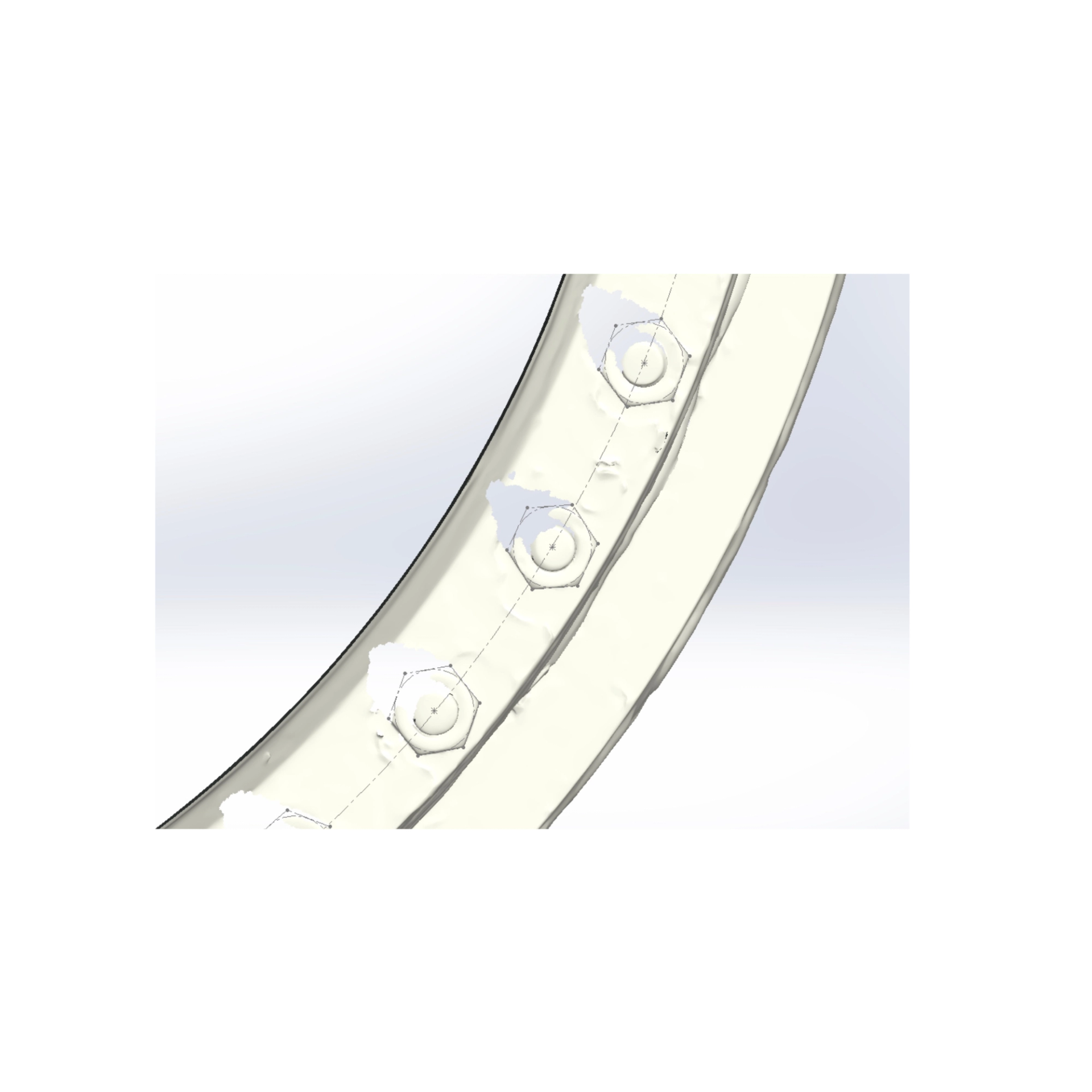
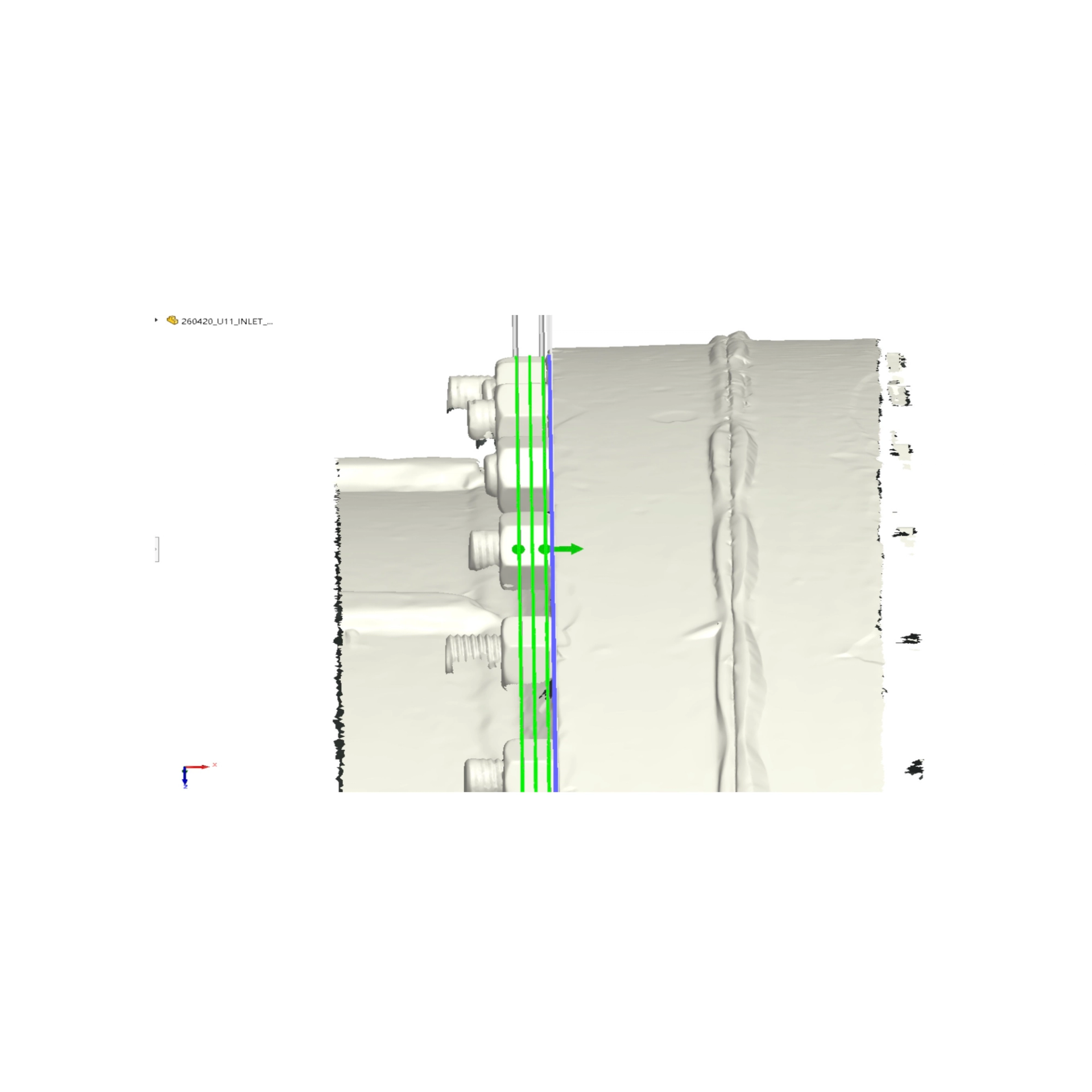
No direct access to the bolt holes: Because the studs and nuts were required to remain installed, the bolt-hole centerlines could not be measured directly. Our engineers instead used the scanned geometry of the installed studs and nuts to determine the hidden bolt-hole locations.
Maintaining the installed condition of safety-related equipment: The heat exchanger heads could not be removed from service, eliminating traditional measurement methods. We performed all measurements in the field using portable metrology-grade laser scanning equipment.
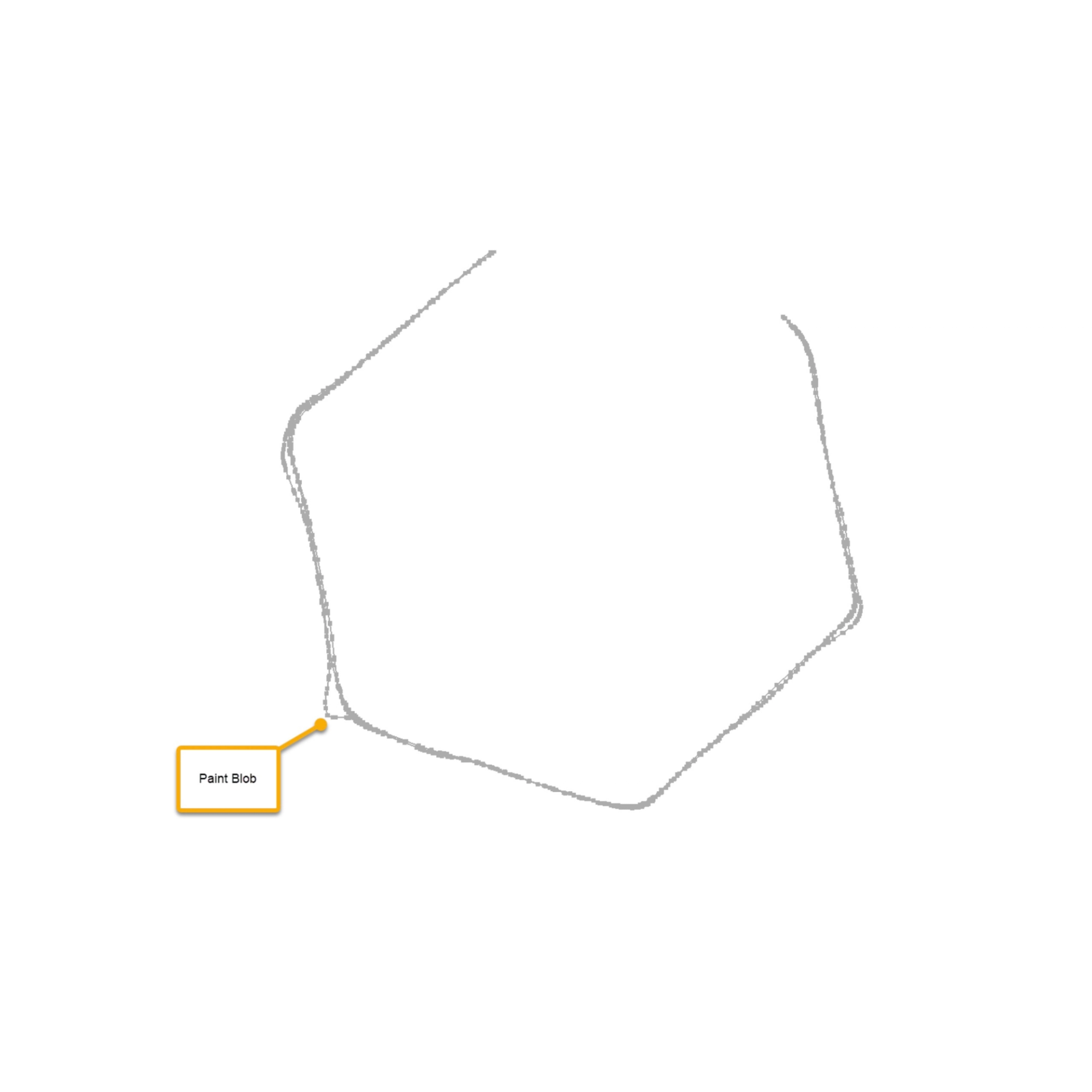
Accurately locating nut and stud centerlines: Multiple cross-sectional analyses were performed through the scanned nut geometry to identify precise center points and establish reliable reference data.
Reconstructing the bolt circle and flange clocking pattern: Once individual nut centers were determined, a best-fit bolt circle was generated to calculate the exact bolt-hole pattern and flange orientation.
Validating the final results: The reverse-engineered CAD models were compared against the original scan data using scan-to-CAD deviation analysis to confirm the accuracy of the final clocking determination.
OUTCOME
The project successfully delivered:
- Precise bolt-hole clocking information for both field-fit welded flanges
- Reverse-engineered 3D CAD models of the heat exchanger heads
- Accurate bolt-circle geometry derived without flange disassembly
- Validated scan-to-CAD models representing the true installed condition
- Engineering data that allowed the client to move forward confidently while maintaining operational continuity
Most importantly, the entire project was completed without removing the exchanger heads, loosening studs, or disturbing any safety-related equipment.
TOOLS & TECHNIQUES THAT MADE A DIFFERENCE
ZEISS T-SCAN HAWK 2
Portable metrology-grade laser scanner used to capture high-resolution field data directly at the nuclear facility.
REVERSE ENGINEERING & CAD RECONSTRUCTION
Detailed CAD models were generated from the scan data, providing a digital twin of the installed equipment.
• CROSS-SECTIONAL GEOMETRIC ANALYSIS
Multiple section cuts through the scanned nut geometry allowed engineers to accurately determine individual nut center points.
• BEST-FIT BOLT CIRCLE CALCULATIONS
Using the calculated nut centers, engineers generated a best-fit bolt circle that revealed the true bolt-hole pattern and flange clocking.
• SCAN-TO-CAD DEVIATION ANALYSIS
Final validation ensured the reconstructed geometry aligned with the measured field condition.
WHY IT MATTERS
Projects involving nuclear, power generation, chemical processing, and other critical infrastructure often present situations where equipment cannot be removed, modified, or taken out of service for measurement.
This project demonstrates how modern metrology and reverse engineering techniques can provide highly accurate engineering data when traditional measurement methods are impossible.
By combining advanced laser scanning, geometric analysis, and CAD reconstruction, HAGLER was able to determine the exact flange clocking of safety-related equipment without disassembly, reducing risk, minimizing downtime, and delivering the confidence needed for critical engineering decisions.
SUPPORT
At Hagler Process, we specialize in providing tailored solutions for industrial processing applications, from equipment selection to system optimization. Contact us today at (423) 265-2281 or sales@haglerprocess.com to discuss your needs and discover how we can help improve your operation.